Configure the Senstar Sensor Fusion

Configure the Senstar Sensor Fusion in the Senstar Symphony Server configuration interface.

For information about specific Senstar Sensor Fusion settings, see the Senstar Sensor Fusion settings topic.

  1. In the Senstar Symphony Server configuration interface, click Devices > Cameras.
  2. Select the camera and click Edit.
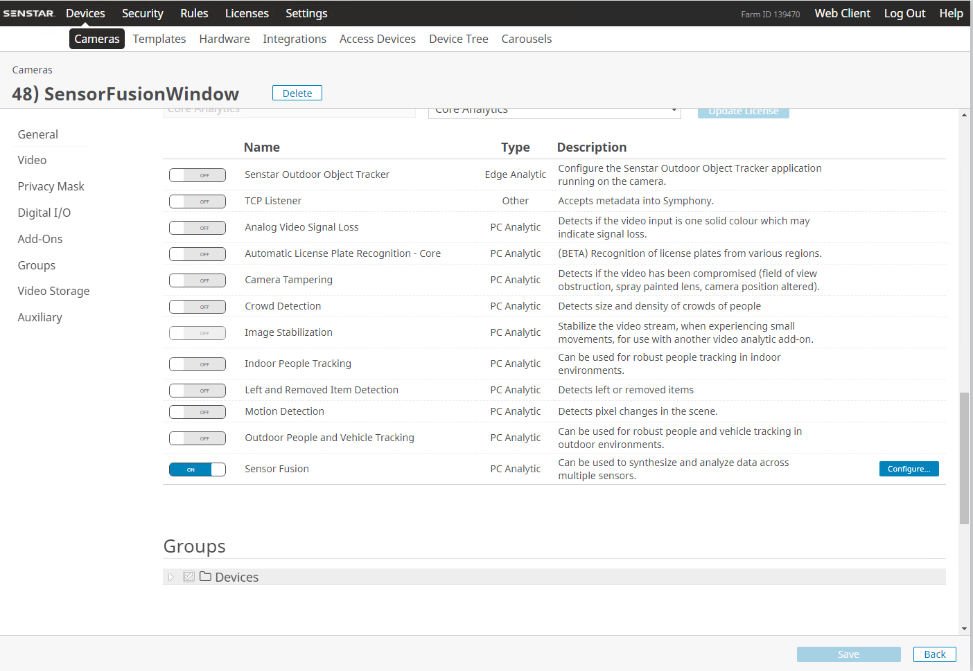
  3. In the Add-Ons list, turn Senstar Sensor Fusion on and click Configure.


  4. In the Overview section, configure the resolution and FPS for the camera.
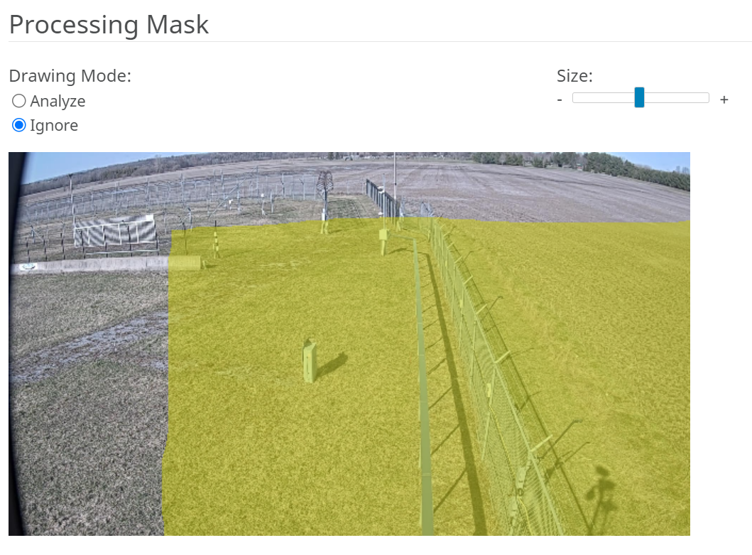
  5. In the Processing Mask section, set the areas in the image that the camera ignores or analyzes.


  6. In the Calibration section, calibrate the camera to the scene.

    Select Automatic to have the video analytic automatically determine the camera position and view information.

    Select Uncalibrated to run the video analytic without camera position and view information.
    Warning: Selecting this option greatly reduces the accuracy of the video analytic.
    Select Manual to manaully set the camera position and view information. You can drag the camera to the correct position or adjust the parameters in the applicable fields. The reference person in the image should match, as closely as possible, the size and position of a real person in the view.

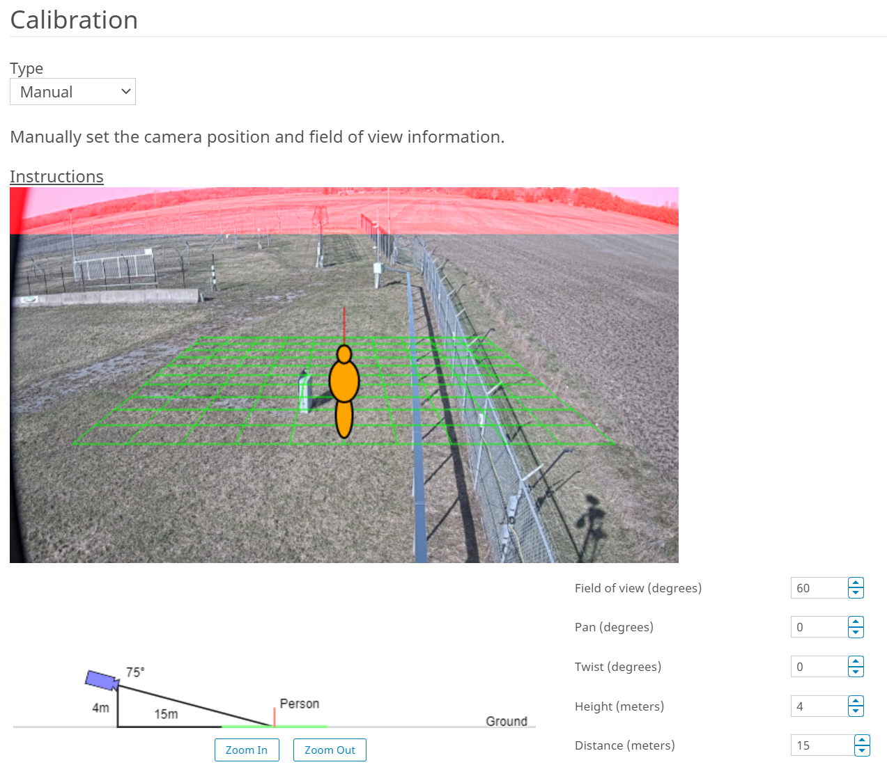
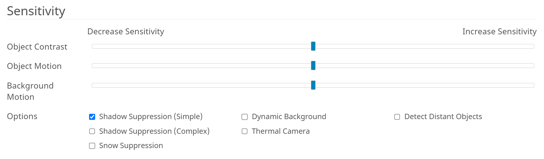
  7. In the Sensitivity section, set how sensitive the Senstar Sensor Fusion is to contrast and motion, and select which options to enable to optimize the camera for the environment.


  8. In the Sensor Segments section, draw the segments of the of the perimeter intrusion detection system.


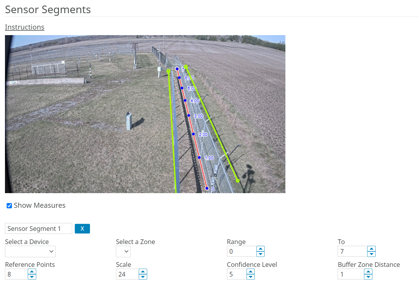
    The sensor segments do not have to cover the entire perimeter intrusion detection system. The coverage of the Senstar Sensor Fusion does not depend on the perimeter intrusion detection system zone configuration; the sensor segments can be part of a single zone, part or multiple zones, or match a zone exactly.

    1. In the image, click and drag to draw a sensor segment that matches both the position and location of the applicable perimeter intrusion detection system zone.
    2. Select Show Measures.
      Displaying measurements is optional, but the measurements make it easier to add sensor segments.
    3. In the Name field, type a name for the sensor segment.
    4. In the Select a Device list, select the perimeter intrusion detection system that provides information to the Senstar Sensor Fusion.
    5. In the Zone list, select the perimeter intrusion detection system zone that the sensor segment matches.
    6. Set the length of the sensor segment in the Range and To fields.

      The Range value should match the starting point of the perimeter intrusion detection system zone.

      Table 1. Example settings
      PIDS zone PIDS length Range value To value
      1 10 0 10
      2 20 10 30
      3 10 30 40
    7. In the Reference Points field, select how many reference points you want on the sensor segment.

      You should add as many reference points as there are fence posts in the perimeter intrusion detection system zone.

      Warning: When you add additional reference points to the sensor segment, the yellow lines that mark the buffer zone will converge on the end of the sensor segment. The buffer zones lines will return to normal once you set the Scale value in the next step.
    8. In the Scale field, adjust the scale of the sensor segment so that the reference points match the fence posts included in the length of the sensor segment.
      Tip: To set the scale correctly, focus on two reference points and adjust the scale so that the reference points in the image match the fence posts.
    9. In the Confidence field, set how confident the Senstar Sensor Fusion must be to raise an alarm.
    10. In the Buffer Zone Distance field, set how far from the sensor segment (and the perimeter intrusion detection system zone) the video analytic looks for objects.
  9. Click OK.
  10. Click Save.