The VE500 interface is displayed only if Symphony has detected the VE500 analytic software on your camera.
Task 1: Configure VE500
In the Client, from the Server menu, select Configuration. The Configuration dialog box opens. This allows you to configure devices for the currently selected server.
In the left pane, click Devices. The Devices dialog box opens.
Click the camera you want to configure for use with video analytics and click Edit.
Click the Analytics Engines tab and select VE500.
Click the Analytics Configuration tab. From the Analytics Engines drop-down list, select Intel_VE500.
(Optional) On the Overview subtab, click the Select Different Image button to select an image from your camera on which to base your analytic configuration.
Using the displayed image from the video, define the area in yellow (a mask) where objects in motion should be detected. For details, see Masks_and_Common_Settings.
Select the Erase option to erase the yellow mask.
Select the Draw option to draw the yellow mask.
The Size slider adjusts the pen thickness.
Option/Design |
Description |
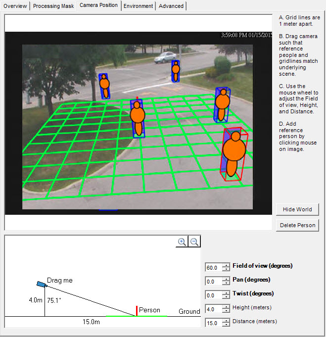
Grid |
Grid lines are 1 meter apart and automatically displayed over the scene. |
Reference person icon |
An orange colored form representing person size and position in an image. Four populate the image automatically. Move the reference people icons to various positions in the image, foreground and background as they would naturally occur. To add more reference person icons, click your mouse on the image. |
Delete Person button |
Removes a reference person icon. Click the reference person icon and then click the Delete Person button. |
Hide/Show World button |
Hides (or displays) the grid lines and reference person icons so that you can view the actual scene in the image. |
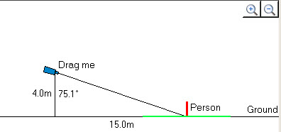
Interactive section |
Allows you to adjust the grid and reference person size to match the underlying scene. Using your mouse, you drag the camera icon up and down, and left and right. |
+/- magnification icons |
Allows you to zoom in and out in the interactive section. |
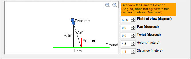
Field of View (FOV) |
Horizontal Field of View.
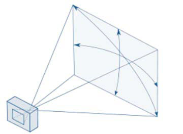
If you increase the value, you must drag the camera icon closer (down) to get the correct person size. If you decrease the value, you must drag the camera icon further away. If you obtain the exact camera position by measuring the actual height and distance, then you must adjust Field of view to make the reference people icons the right size in the scene. Mouse wheel perspective control Allows you to control the amount of perspective in the scene without changing the overall scale. Allows you to make a person icon a certain size while changing the Field of view so that the tilt of the other people icons and their relative size is correct. Position the mouse over the little diagram. Rotate the mouse wheel to increase or decrease the Field of view in 2.5 degrees increments, creating an opposite proportional change in the ground distance parameter. Example: Ground distance is 10.0 m and the Field of view is 60°. One mouse wheel click changes Field of view to 62.5° and ground distance to (60/62.5)*10.0 = 9.6 m. A mouse wheel click in the other direction changes Field of view to 57.5° and ground distance to (60/57.5)*10.0 = 10.43 m. |
Pan |
Movement of the camera from left to right, or right to left around the imaginary vertical axis that runs through the camera. When the camera is pointed at the ground, it basically tilts the ground plane. When the camera is closer to horizontal, it looks more like a rotation of the ground plane. Most useful in a near-overhead view when the camera is pointing off to the side (that is, the deflection from vertical is not completely on the camera view’s up-down axis). |
Twist |
Rotation of the camera around the axis that extends directly out of the camera through the center of the view. Useful in an angled view when the camera is twisted a bit so that a vertical line in the world does not correspond to up-down in the image. Also useful if the ground in the image appears to tilt a bit from left to right. |
Height and Distance fields |
Values correspond to the movements of the camera icon in the interactive section. |
Warning message |
Symphony displays a warning message if the camera angle does not agree with Overhead selection. |
Common
Option |
Description |
Background learning duration (seconds) |
Determines the approximate length of time it will take a foreground object that becomes stationary to merge into the background. Important: If an object has periodic movement with a period greater than the specified time, then that object will always be considered a foreground object (never merged into the background). The background is updated all the time, not only when the analytic engine starts. |
Option |
Description |
Method |
• % of screen change: Monitors the percentage of the scene that is considered foreground. If the amount of foreground is too high, model relearning is triggered. • Brightness change: Monitors the scene for abrupt, overall changes in brightness of, conceivably caused by a change in lighting or a weather event. • Spectrum change: Monitors the scene for abrupt, overall changes in brightness, but less sensitive to local changes. Such as a person in a dark coat walking by. • Combined change: A combination of % of screen change and Spectrum change. |
Sensitivity |
Value range between 0 and 100. A high sensitivity means the relearning is easily triggered. For example, 80 sensitivity will trigger when just 20% of the screen is foreground, while a low sensitivity triggers relearning only in an extreme situation. |
Time to wait before resuming tracking (seconds) |
Allows you to set how long to wait before resuming to track objects. Ideally this value should be zero, but if you are aware of a lighting issue where tracking immediately can cause false alarms, then set this to the number of seconds needed for the light to stabilize before tracking starts. |
Option |
Description |
Shadow/Illumination Removal |
Disabled by default. |
Strength |
A high sensitivity level setting is helpful in cases where you have a very strong dark shadow. Disabled by default. A low sensitivity level setting is help in cases where you have a light shadow. Example: 0.1 = a light shadow 1.0 = a very strong dark shadow |
Object Contrast |
Controls how sensitive the background model is to perceived similarities between the background and objects. If an object in the camera view appears similar to the background (such as a dark background and a person in dark clothing), increasing the object contrast threshold increases the model’s ability to detect the object against the dark background. |
Snow Detection |
Enable this option to configure the background model to detect and track in areas covered by snow. Disabled by default. |
Option |
Description |
Analysis FPS |
Indicates how many frames will be analyzed by the system. Typically the default value should not be altered. However, in many cases the analysis frame rate can be reduced to conserve CPU. Doing this may negatively alter the algorithm’s performance. |
Capture Resolution |
Displays the resolution at which the video is being recorded. This can be changed in the Device setup. |
Analysis Resolution |
Setting the Analysis Resolution the same as the Capture Resolution ensures that objects will be detected as far away as possible. However, in order to conserve CPU resources, it is possible to down sample the video sent for analysis. Downsampling will reduce CPU requirements, but may also reduce the detection range of the video analytic. |
The Advanced subtab settings are for experts only. Values should be changed only in cases where the analytic engine is not functioning as expected.
For VE180 Outdoor Object Tracking, see Aimetis Knowledge Base article #10306 VE180 Outdoor People Tracking.
Task 2: Create a Rule using VE500
1. From the Server menu, select Configuration > Rules.
2. Click New. The Rule Wizard opens. Read the overview and click Next.
3. Select the check box next to the camera name. If it is a PTZ camera, select the Camera Tour Position check box.
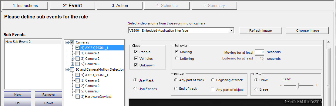
4. From the Select video engine for those running on camera drop-down list, select VE500.
5. For a digital fence, select the Use Fences option:
a. Select the Any Fence option and draw a line over the image with your mouse. Arrows, which are automatically displayed when you draw a line, define which direction the offending object must pass through in order to cause an alarm.
b. With the Any Fence option selected, click the arrows to change their properties.
• Red indicates that an object crossing the line in the arrow direction will cause an alarm.
• The green arrow denotes that an object crossing the line in the arrow direction will NOT cause an alarm.
• Multiple fence lines can be drawn.
If All fences has been selected, the object must cross through all fences drawn to cause the alarm. |
• To delete a line, select the Erase Line option and left-click on the endpoint of the line you want to delete in the image.
6. To designate an alarm zone, select the Use Mask option.
• Select the Erase option to erase the red mask.
• Select the Draw option to draw the red mask.
• The Size slider adjusts the pen thickness.
The following settings apply only to alarm zones:
• Any part of track denotes the object can be anywhere in the red alarm zone to trigger an alarm. To alarm on objects moving anywhere in the alarm zone, select Any part of track.
• End of track denotes that the object has stopped in the alarm zone. To alarm on objects entering the alarm zone and stopping in it, select End of track.
• Beginning of track denotes that the object started moving in the alarm zone. To alarm on objects that were in the alarm zone and started to move, select Beginning of track.
• Any part of object denotes that any part of the object can be anywhere in the red alarm zone to trigger an alarm.
7. Click Next to complete the Rule Wizard.