Aero- Reader Properties
To access the reader properties, go to the Hardware Manager in Symphony AC and unlock the module. After you have added the Aero driver and controller, you should see a reader associated with the Aero controller. Click on the reader and the Properties Window should appear.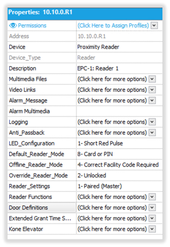
IMPORTANT NOTE: These properties apply to version 1.1.x and higher. Below is the list of Reader Properties for the Aero hardware.
- Address: The address for the reader is automatically assigned within Symphony AC.
- Device: Select the type of reader that will be used.
- Device_Type: This is set to ‘Reader’ and cannot be changed.
- Description: Enter a description for the device to easily identify the location or function of the device. The description will display on the Event Manager module any time an event occurs with the device.
- Multimedia Files: Video/Media that can be associated to the device and called up by right-mouse clicking on the events related to this device.
- Video Links: Associate a camera when the reader becomes active. Used to setup recording on a camera during certain event(s). Please note you must be licensed for the video module to utilize this feature.
- Alarm_Message: A text field that is associated to the device when it goes into alarm state. This text field should be informative in describing what type of alarm it is or what action needs to be taken.
- Alarm_Multimedia: This will play a sound the reader goes into an alarm state. Note: this feature requires the use of a sound card and speaker installed on the computer. To select the Alarm_Multimedia for the device, click on the drop-down arrow to the right of the Alarm_Multimedia tag and select a wave file.
- Logging: Allows for device specific logging. Select the related event then select a Log Type. Click on the Save button.
- Anti-Passback: When Anti-Passback in enabled, the HID/VertX master controller and all readers connected to it via sub-controllers are aware of the cardholder’s whereabouts. When an access granted event is generated, the user is moved into the ‘Area’ where the reader has been assigned to. The user can then present their card to any reader from the next ‘Area’ but cannot present it again to the same reader. Please use the ‘Symphony AC: Aero Anti-Passback’ document for configuration options.
- LED Configuration: To select the LED status, click on the drop-down arrow and select the desired mode.
- Default_Reader_Mode: This mode will determine the default state that the reader will be in when not in an unlocked schedule. The Default_Reader_Mode number will appear on the Hardware Status screen to the right of the sub-controller type. To configure the Default_Reader_Mode click on the drop-down arrow and select one of the following:
- 1-Disabled: This mode completely disables the reader and NO access will be granted.
- 2-Unlocked: This mode unlocks the reader. Using this mode the reader will be unsecured, free ingress and egress is allowed.
- 3-Locked (No Access, Allow REX): This mode secures the door, NO access will not be granted; however free egress will be allowed.
- 4-Correct Facility Coded Required: This option does not do a database check to verify if the card holder has access to the reader. This option checks the cards facility code; if the facility code matches what has been entered for the system then the card holder will be granted access.
- 5-Card Only: This mode requires a card be presented to the reader gain access.
- 6-PIN Only: This mode requires a PIN number be entered on a keypad reader to gain access.
- 7-Card and PIN: This mode requires that a valid card be presented to the reader as well as a valid PIN number. If both instances do not occur, the card holder will not be granted access.
- 8-Card or PIN: This mode allows the card holder to present their card or enter a valid PIN number to gain access.
- Offline_Reader_Mode: When communication between the Controller and Sub-Controller has been lost, the Offline_Reader_Mode instructs the reader in what manner to behave until communication has been reestablished. To configure the Offline_Reader_Mode, click on the drop-down arrow and select one of the following:
- 0=No offline Mode: In the event of a loss of communication between the Controller and the Sub-Controller, this mode states that no offline mode will be enabled. In this mode, the reader will be secured.
- 1=Lockdown (No Access, No REX): In this mode the reader will be locked down, no access into our out of the reader will be allowed. This mode is not a mode to be used on exterior doors.
- 2=Unlock: In this mode the reader will be unlocked allowing free ingress and egress.
- 3=No Access, Allow REX: In this mode, the reader will be disabled for card use, but will allow free egress.
- 4=Correct Facility Code Required: This is the default programmed mode. Using this mode, there is no database check done to verify if the card holder has access to the reader. This option checks the cards facility code; if the facility code matches what has been entered for the system, the card holder will be granted access.
- Override_Reader_Mode: When communication is lost between the Controller and the Sub-Controller and the reader is on a timed unlock schedule, the Override_Reader_Mode dictates what state the reader will go into until communication has been reestablished. To configure the Override_Reader_Mode, click on the drop-down arrow and select one of the following:
- 1-Disabled: This mode disables the card reader. If a card is presented to the reader the Event Manager will display a Reader Not Enabled Message.
- 2-Unlocked: This mode unlocks the reader. Using this mode, the reader will be unsecured, free ingress and egress is allowed.
- 3-Locked (No Access, Allow REX): This mode secures the door, card access will not be granted; however free egress will be allowed.
- 4-Correct Facility Coded Required: This option does not do a database check to verify if the card holder has access to the reader. This option checks the cards facility code; if the facility code matches what has been entered for the system the card holder will be granted access.
- 5-Card Only: This mode requires a card be presented to the reader to be granted access. Using this mode, no pin code is required.
- 6-PIN Only: This mode requires a PIN number be entered on a keypad reader to be granted access.
- 7-Card and PIN: This mode requires that a valid card be presented to the reader as well as a valid PIN number before access will be granted. If both instances do not occur, the card holder will not be granted access.
- 8-Card or PIN: This mode allows the card holder to present their card or enter a valid PIN number to gain access to the reader.
- Reader_Settings: This option allows the configuration of single, paired, or elevator readers. To configure the Reader_Settings, click on the drop-down arrow and select one of the following:
- 000= Single Reader: This option is the default reader setting and configures the reader for a single reader mode.
- 001= Paired (Master): When two (2) readers with one set of locking hardware will be utilized, this reader_setting configures the reader as the primary reader for entry.
- 002=Paired (Slave): When two (2) readers with one set of locking hardware will be utilized, this reader_setting configures the reader as the secondary reader for exit. When this reader setting is used, to unlock a door, the “unlocked” reader command must be sent from the ‘Master’ reader.
- 003=Turnstiles
- 004=Elevator Reader (No feedback): This reader_setting configures the reader to be an elevator reader with no floor selection option.
- 005=Elevator Reader (No Feedback): This reader_setting configures the reader to be an elevator reader with floor selection, the use of an Input board is required in order to utilize this feature.
- 101 – Paired (Master: Normal Access Reader)
- 102 – Paired (Master: RSI Handkey – II Reader)
- 103 – Paired (Master: Identix FingerScan)
- 104 – Paired (Master BioScrypt FingerScan)
- Door Definitions: This option allows for the hardware points to be selected for the Door. Points can be disassociated allowing a point to be used for other functions. For example, if the door contact is set to a value of none, that point (input) can now be configured as a monitor point for other use. To configure the Door Definitions, click on the drop-down arrow to the right of the Door Definitions tag. Each hardware point for the door is assigned to the default addresses as the following:
- Reader 1 Door Contact = I1
- Reader 1 REX = I2
- Reader 2 Door Contact = I3
- Reader 2 REX= I4
- Reader 1 Door Strike = O1
- Reader 1 Door Sounder = O2
- Reader 2 Door Strike O3
- Reader 2 Door Sounder O4
- Extended Grant Time Setting: This feature is used in conjunction with the ADA mode (American Disability Act). If a card holder record has been tagged with the ADA mode flag and such card is presented at the reader, the card holder will be granted additional time for access through the door.
- Kone Elevator: Custom Elevator technology. Please contact technical support for further details. (support@Senstar.com)