Aero- Input Supervision
What are Inputs?
Inputs are devices typically used to monitor, such as door contacts, motion sensors, temperature sensors, and request to exit buttons. Inputs SEND information to the Symphony AC software. Inputs can be used to generate alarms, but you can also mask them during specific time periods. When Inputs are masked, you will still see notifications for the Inputs, but they will not generate an alarm. You can choose when to mask Inputs (i.e. after work hours or during weekends) to eliminate false alarms.
A. Configuring Input Supervision in Symphony AC
- Open “Hardware Manager” and unlock the module to display the “Properties” pane.
- Expand the Hardware Tree list until you see the Input that will be configured.
- In the “Properties”, you will the following options (See Figure 1):
- Permissions: Select which profiles can view this profile.
- Device: Input Device Type.
- Device_Type: Leave as is.
- Description: Enter a description for this input.
- Multimedia Files: Select a video file that will be displayed when the input is active.
- Video Links: Assign a camera that will be displayed when the input is active.
- Alarm_Message: Enter a message that will be displayed when this input is active and being logged as an alarm.
- Alarm Multimedia: Select and video that will be displayed when the input is active and being logged as an alarm.
- Google Earth Link: Not Used
- Logging: Configure custom logging for this input.
- Hold_Time: When the input becomes active (alarm or trouble condition), the Hold Time begins counting down. If the input goes normal before the hold time ends, the input will wait to report normal until the hold time ends. If the input goes normal after the hold time ends, the normal status is reported immediately.
- Debounce_Time: A sensitivity setting. A low debounce setting requires the system to receive this number of consecutive reads from an input prior to reporting a change of state (i.e Alarm or Input Active).
- Input_Supervision: This allows you to designate whether a point is supervised or unsupervised. The system needs to know when the input point is in a normal condition and when it is in an alarm condition (NO/NC).
- Latch_Mode: There are three options: Normal, Latching, and Non-Latching. Latching is the manual use of electronic access control credentials in which one credential read causes a lock to unlock and a second read locks the lock. The lock changes state only after a credential is read.
- Entry_Delay: The amount of time an input point can remain open before an alarm is activated. The default setting is 0 seconds, but the user may set this up to 255 seconds.
- Exit_Delay: The amount of time a point can be unmasked before being reported as an alarm. The default setting is 0 seconds, but the user may set this up to 255 seconds.
Figure 1 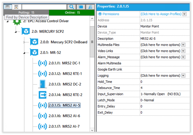
- Click the “Save” button to finish. If controller is Online, changes will take effect immediately. If controller is Offline, download “Controllers and Devices” database once the controller comes Online.
B. Input Monitoring in Symphony AC
Input Address: Devices for Aero panels in Symphony AC are addressed in the following format:
2.0.1.I5
2: Driver Number
0: Controller Number
1: Sub-Controller Number
I: Abbreviation for “Input”
5: Input Number
Input Status: You can see the status of Inputs from multiple locations within Symphony AC such as “Point Status” or “Graphic Maps”. In the example below, we will use the “Controller Status Screen”. Your controller MUST be online for the status to display.
While you are in Hardware Manager, click on a controller from the hardware tree list, you will see all devices connected to the controller and all sub-controllers (assuming the controller is online). You can see each controller’s address, model and current reader mode. Under each sub-controller, you have 2 rows of blocks. Top blocks are “Inputs” and bottom ones are “Outputs”. The blocks will change color depending on the state of the input. (See Figure 2)
Green: Input is inactive
Light Green: Input is masked and inactive
Red: Input is active
Light Red: Input is masked and active
Yellow: Input has Fault. Go to “Event Manager” or “Alarm Manager” to see which of the following is causing this issue:
- Grounded
- Shorted Loop
- Open Loop
- Foreign Voltage
- Oscillating Voltage
Figure 2 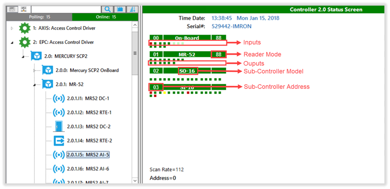
C. Masking Inputs in “Device/Group Areas”
- Open “Device Groups/Areas” and unlock the module.
- Select the controller where the Inputs are connected to.
- Click in the “Monitor Points” tab and select the Inputs that will be masked.
- In the “Device Groups/Areas” pane, click on the next available Area. Right-click on the Area and select “Add Selected Input(s) to the Group/Area”
- In the Properties pane, select the time schedule which will be used to mask the input(s).
- Click the “Save” button then the “Download” button to finish. (See Figure 3)
Figure 3 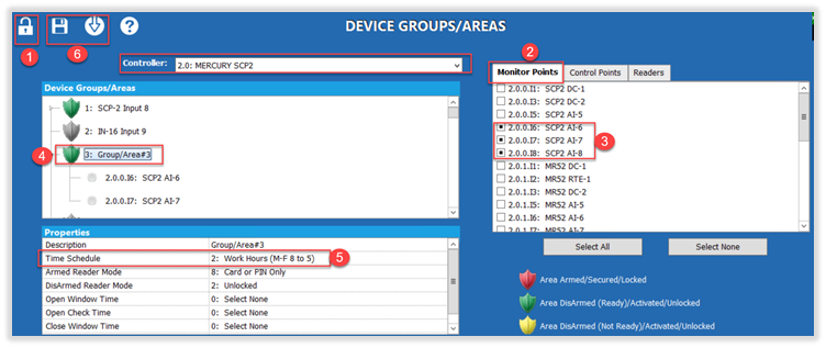
D. Troubleshooting
Below are some troubleshooting issues.
- Cannot change “Device Type” for input:
- Some Inputs are associated with doors and must be removed from the “Door Definitions” properties found in the reader.
- Input is not displaying any events/alarms:
- Check hardware- Wiring, device (Door Contact, Sensor etc.).
- Make sure controller is online.
- Verify logging is enabled for input.
- Make sure input is not being “masked”.
- Input is not displaying correct status:
- Check “Input-Supervision” setting in the input properties.
- Check hardware- Wiring, device (Door Contact, Sensor etc.)