Aero- Hardware Setup Guide
The following guide provides steps to configure and initialize the Aero IP controller panel in the Symphony AC Software. Use this guide as a quick reference. Please contact Senstar Corporation for questions.
Considerations Prior to Setup
- Please ensure that you are NOT using a legacy Aero panel (i.e. you are NOT using the SCP-C, SCP-E, or SCP-S panel). This guide will assist you in setting up the EPC-1, SCP-2, SCP-M, LP1501, LP1502, LP2500, and LP4502 controllers.
- Make sure you add Symphony AC and all sub-folders files to the anti-virus exclusion list.
- Port 3001 must be opened to allow communication between the Aero controller and Symphony AC.
Setting Up the Aero IP Hardware
I. Configuring the IP Address of the Aero Controller
- Disconnect power to the Aero Controller (EPC-1, SCP-2, SCP-M, LP1501, LP1502, LP2500, and LP4502).
- From a PC or Laptop, connect directly to the controller via a cross-over cable.
- To connect to the controller configuration page, configure your PC network settings to the following: (See Figure 1)
Figure 1 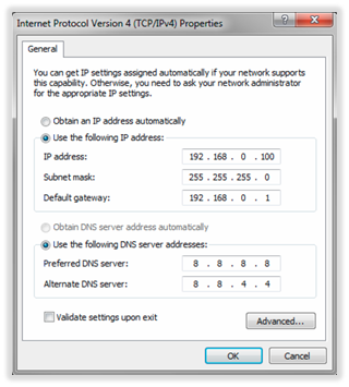
- Flip all 4 DIP switches to the “ON” position and connect power to the controller.
- Open a web browser and type: http://192.168.0.251 to open the controller page.
Note: If you receive a certificate warning, ignore the warning and proceed to the webpage
Click the “Click Here to Login” button to proceed to the login page.
- Enter the username and password to login the controller. (See Figure 3)
Figure 3 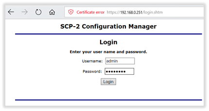
If you do not know this information, you can log in using the default username and password:
User Name: admin
Password: password
Note: For firmware version 1.90 and later, if you are going to log in using the default username and password, you must login within five (5) minutes of flipping all DIP switches to the “ON” position. If more than five minutes have passed and you cannot log in using the default username/password, you will see the following message stating that the default login procedure failed because the current time window has expired. (See Figure 4)
Figure 4 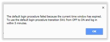
Toggle dip switch #1 from ON to OFF to ON one (1) time (make sure it is on the “ON” position at the end of the cycle) and you will have another five (5) minutes to log in using the default username and password.
Note: For earlier firmware versions, you may have to toggle dip switch #1 from ON to OFF to ON three (3) times if you do not log in within five (5) minutes.
- From the main menu pane, click on the “Network” button to view the Network Settings (See Figure 5)
Figure 5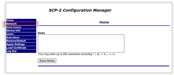
- In the Network Settings window, complete the following:
- Select “Use Static IP Configuration” and enter your network parameters.
- Click the “Accept” button.
- From the main menu pane, click on the “Users” (See Figure 6)
Figure 6 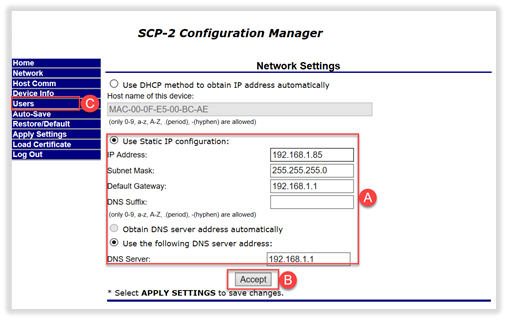
Note: Creating another account eliminates the need to do the default log in procedure to connect to the controller. This is not required, but highly recommended. If you want to skip this, from the main menu pane, click on the “Apply Settings” button and skip to step 12.
9. In the Users window, click on the “New User” button. (See Figure 7)
Figure 7 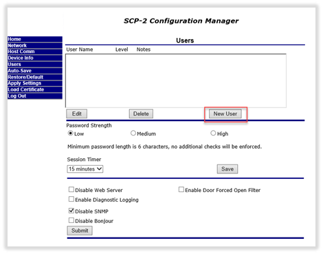
10. The User Account window will open. Enter the following:
- Select account level: Leave at “1”, this will grant you the highest permissions.
- Username: Enter a user name
- Password: Enter a password
- Password again: Enter the same password
- Notes: Enter any notes you would like for this user account.
Click the “Save” button. (See Figure 8)
Figure 8 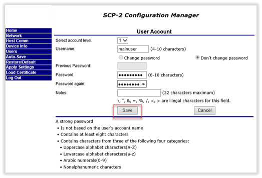
- You will return to the Users window and you should now see the newly created user account. From the main menu pane, click on the “Apply Settings” (See Figure 9)
Figure 9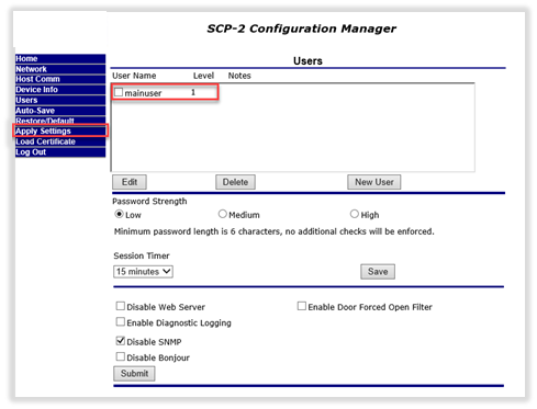
- In the Apply Settings window, click on the “Apply Settings, Reboot” button. (See Figure 10)
Figure 10 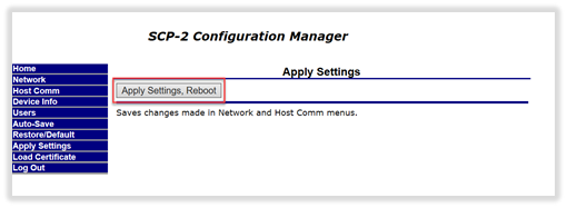
- After clicking on the “Apply Settings, Reboot” button, a new webpage will load. Click/check all the boxes and under “Do you wish to proceed”, click “YES.” (See Figure 11)
Figure 11 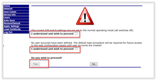
- Once the controller finishes the reboot procedure (Note: This may take approximately one minute), complete the following:
- Disconnect the power to the controller.
- Flip all 4 DIP switches to the “OFF” position.
- Connect power and network cable to the controller.
- After the controller boots up, ping new IP of controller.
- You can revert your network settings on your PC.
II. Adding the Aero Driver
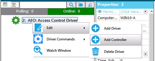
- Launch Symphony AC and navigate to the “Hardware Manager” module. Click the “Unlock” button to unlock the module and allow editing.
- Right-click on the Hardware Tree pane and from the pop-up menu select “Edit” then “Add Driver”.
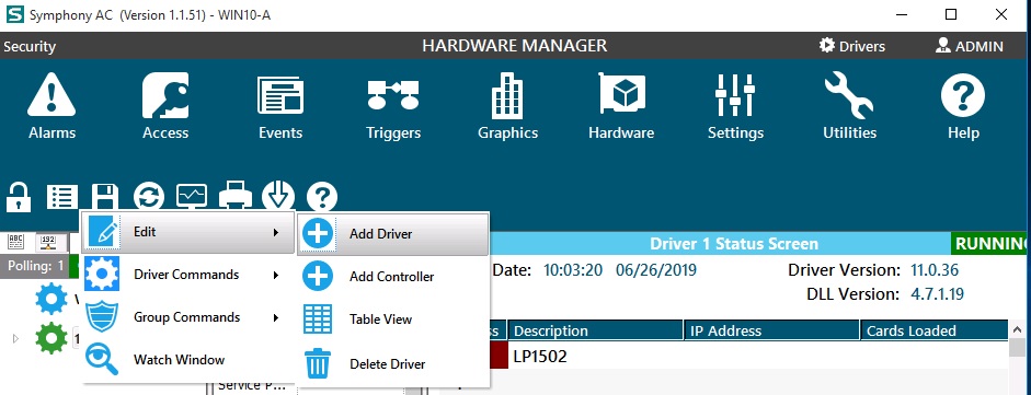
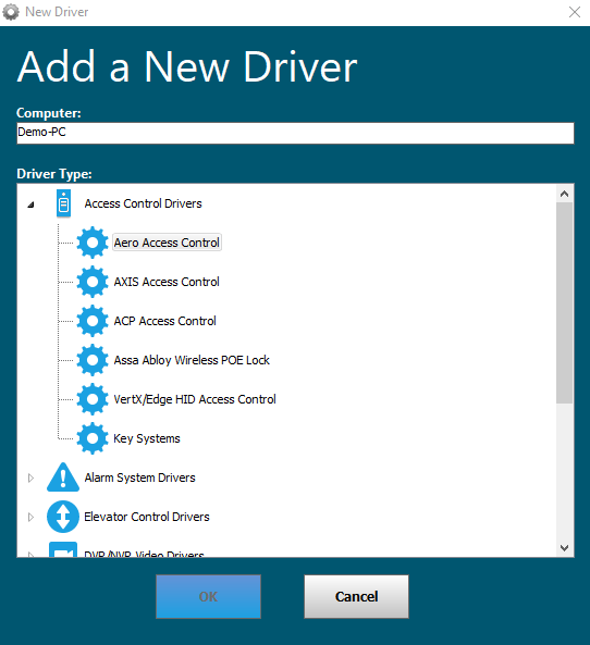
- The “Add a New Driver” window will open.
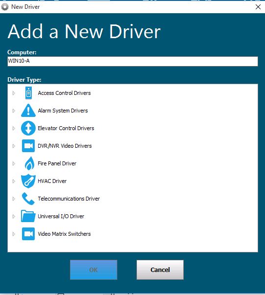
- Click on Access Control Drivers and select “Aero Access Control” then click the “OK” button to finish.
- Refresh the Hardware Tree pane and click on the Aero Driver to view the driver properties pane.
- A 'Driver' runs as a Windows Service. Set the Windows User Account that will be used to run the Aero Driver. Leave these fields blank to use the 'LocalSystem' account.
Service UserName: Enter the Windows User Name.
Service Password: Enter the password for Windows User Account.
Click Save.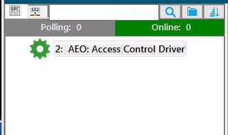
Note:The Windows User Account needs to have rights to run Windows Services.
If using a Windows Domain Account, enter the full account name. In the example below, the Domain name is “SenstarCORP” and the Windows User account is “Administrator”. (Senstar\Administrator).
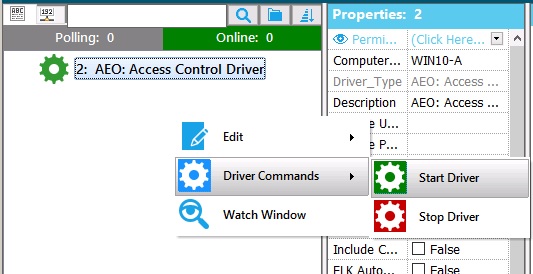
- From the Hardware Tree pane, right-click on the Aero Driver and from the Driver Commands menu select “Start Driver”. The gear icon for the Aero Driver and the “EPC” box in the System Information window will turn ‘green’.
- Open the Windows Services application and find the “Senstar- Aero Driver” service. The “Status” should show as “Running” and “Log On As” should display the Windows User Account entered in step 6.

III. Adding and Configuring Aero Controller in Symphony AC
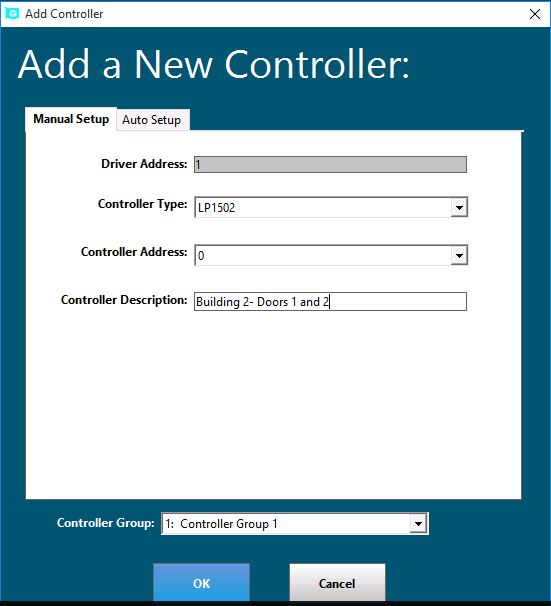
- From the Hardware Tree pane, right-click on the Aero Driver and from the “Edit” menu click on “Add Controller”
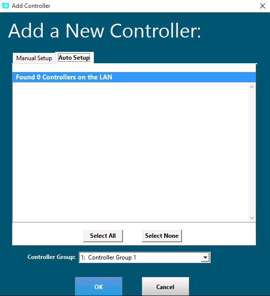
- In the Add a New Controller window, there are 2 ways to add a controller: a) You can manually add it if you know the IP address of the controller or b) you can use ‘Auto Setup’ which will search the local network for any Aero devices. Note: Auto Setup will ONLY detect controllers on the same subnet as the Symphony_AC Server hosting the Aero Driver.
- To Manually Add Controller: In the “Add a New Controller” window, enter the following:
- Driver Address: Leave as is.
- Controller Type: Select the appropriate controller model/type, ie “LP1502”.
- Controller Address: This will automatically select the first available address. You can select another available address if you wish.
- Controller Description: Enter the controller name/description here. (Note: You may edit the name/description later)
- Controller Group: By default, Controller Group 1 is selected. If this controller belongs to another Controller Group, select it from the dropdown menu. (Note: You may edit the Controller Group later)
- Click the “OK” button to finish.
- To use the ‘Auto Setup’ tool: In the “Add a New Controller” window, complete the following:
- Click on the “Auto Setup” tab.
- The network scan will automatically begin.
- Once the scan completes, select the controller(s) that will be added.
- Click the “OK” button.
- You will get the following notification(s) for every controller you selected to add:
- Is controller “X” an EPC-1? If so, click “Yes” and the window will close unless you selected more than 1 controller to be added. If it is not, click “No” and continue to the next step.
- If you clicked “No” you will get another notification asking if controller “X” is an SCP-2. If so, click “Yes”, or if it is not, click “No”. The window will now close unless you selected more than 1 controller to be added.
- Refresh the hardware tree and select the newly added controller to view the controller properties.
Note: If you added more than 1 controller using the ‘Auto Scan’ tool, do the following for every controller, in the Properties pane, ONLY change the following properties:
- Description: Enter the description for this controller.
- Poll: Uncheck the box so that it reads “False”.
- Channel: (New window will pop out)
- Channel: Leave as is
- Port: Leave as is (3001 is default port)
- Baud Rate: 38400
- Time Out: 1000
- Retry: 10000
Click “OK” to close the window.
Note: You will get a message that will let you know that a driver restart will be required. Click “OK” to the message. If you get a message asking to download changes, click “No”.
- Card Formats: Click on the Card Formats field and a new window will open. Select the card format(s) that will be used. Close the window to finish.
- Click on the “Copy Card Format” button.
- Select “Wiegand” to open a list of the pre-defined formats.
- Select the Card Format that will be used.
Note: There are 8 Format tabs, you can select up to 8 different formats per controller.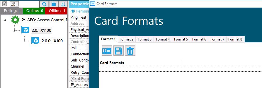
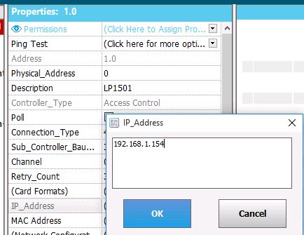
- IP_Address: Manually enter the IP address of the controller (DO NOT COPY/PASTE). If you used ‘Auto Setup’ to add the controller, the IP address will already be entered.
- Daylight_Saving: If applicable, select Daylight Saving zone.
- GMT_Offset: Set GMT offset.
- Offline Sensitivity: Verify it is set to “Not Sensitive”.
- Model: Select Aero controller model (Default is “SCP-2”). If you used ‘Auto Setup’ to add the controller, verify the correct model is selected.
- Restore to Last Known State on Re-Reconnect: Verify the box is NOT checked so that the value displays as “False”.
- Click the “Save” button to finish.
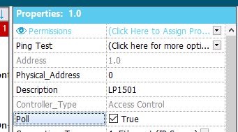
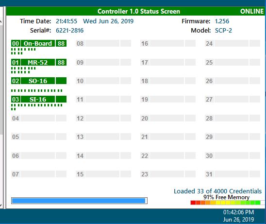
- In the controller properties pane, check the “Poll” box so that it reads “False” then back to "True" and wait a few seconds for the controller to come online. In the Controller Status Screen, you should see the following: Time/Date, Firmware, Serial, Model and On-Board readers. Note: If the controller does not come online, please go to Section IV for troubleshooting.
- In the Hardware Tree pane, select and right-click on the controller. From the “Controller Commands” menu, select “Set Date and Time”. The time/date in the Controller Status Screen should be updated to the current date/time.
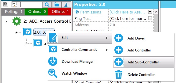
- If you have sub-controllers (MR50, MR52 etc.), right-click on the controller and from the “Edit” menu select “Add Sub-Controller” and a new window will open. Note: If you do not have sub-controllers skip to step 11.
- In the “New Sub-Controller” window click on the ‘Auto Setup’ tab. This will scan the RS-485 line and search for sub-controllers. Once the scan is finished, click the “Add Sub-Controller” button to add the Sub-Controllers.
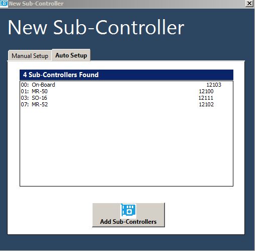
- Refresh the Hardware Tree pane and click on the controller. You should now see the sub-controllers.
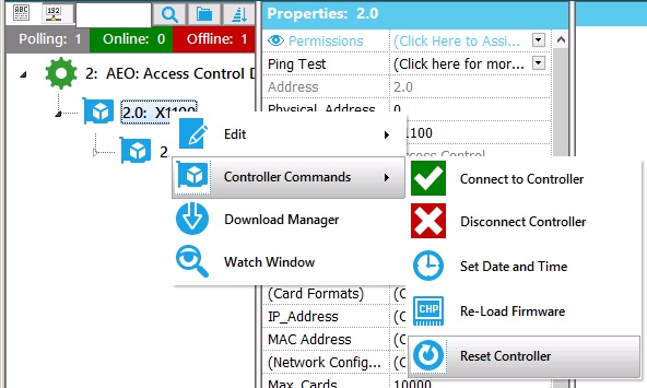
- Select and right-click on the controller. From the Controller Commands menu, select “Reset Controller. Note: The controller will go offline for a moment and then do several downloads.
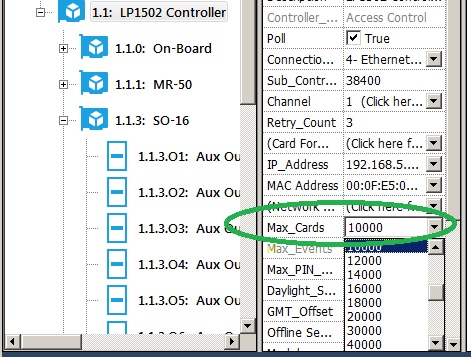
- Memory Reset: Once the controller comes back online and all downloads are complete, click on the controller to view the controller properties pane. Click on the Max_Cards field and select the approximate the number of cards that will be loaded into the controller. Note: Always use a higher number than the number of cards you expect to be loaded to the controller. For example, if you expect 10,000 cards, select 12,000.
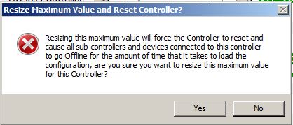
- You will receive a message asking if you are sure you want to resize the maximum value for the controller. Click “Yes” and the controller will go offline for a moment and perform several downloads.
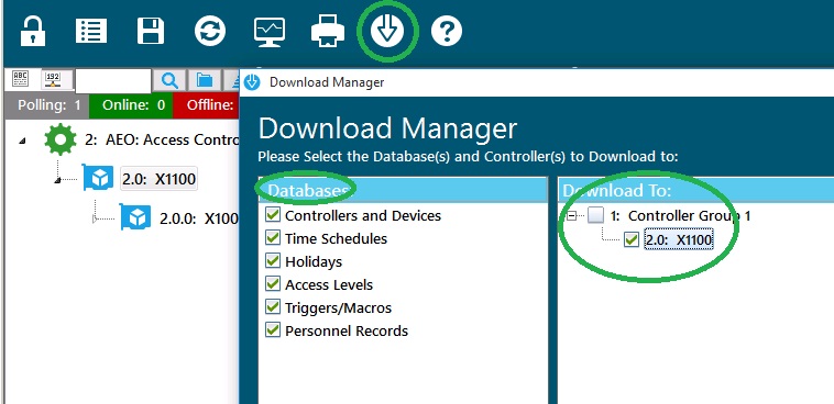
- Once the controller comes back online and all downloads are complete, open the “Download Manager”, select ALL databases and perform a download to the controller. The controller will go offline for a moment and then do several downloads.
- This process is now complete.