Aero- Controller Properties
Each hardware device has its own set of properties that can be configured to allow the operate to customize the hardware to meet their needs. To access the properties window, add the appropriate driver and controller in the Hardware manager. Click on the Aero controller and click on the unlock button to view the controller properties.
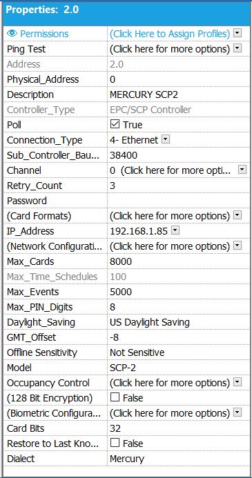
Below is a list of controller properties in hardware manager when using Aero hardware. After making changes, click the save button (i.e. floppy disk).
- Ping test – Performs a ping test to the controller to verify network connectivity.
- Address– The Address field displays the driver number the controller is assigned to in the first digit and the controller address in the second digit. For example, 2.0 would be driver 2 controller 0.
- Physical_Address– The software will auto-assign a virtual address to the controller. This number should not be changed.
- Controller_Type– This value will be automatically selected if the controller was added using the Auto-Setup feature (this feature will be grayed out and non-configurable). If the controller has been added manually, the operator must designate the type of device to add.
- Poll– Check box value to determine whether or not communication attempts to be made to this controller. With the box checked, communication will be attempted. When the box is checked or unchecked, the driver will need to be stopped and restarted before the changes are made.
- Connection_Type– The type of connection that will be used to communicate to the controller (Serial, Ethernet, Dial up). For best performance, Ethernet is the recommended connection type. To select the connection type, click on the drop-down arrow to the right of the Connection_Type tag. Highlight the desired connection type from the list provided and click OK to save the changes.
- Sub_Controller_Baud_Rate– The speed in which the controller will communicate to its sub-controllers. This speed is generally set to 38400, However, the speed may be reduced for intermittent communication failures. This value must match the value programmed into the controller device. If the two values do not match, communication to the sub-controller will not be available. To select the baud rate, click on the drop-down pick list located to the right of the Sub_Controller_Baud_Rate tag and select the baud rate.
- Channel– Defines the communication pathway between a driver and a controller. (Multi-drop is achieved by assigning the same channel to 2 controllers.) To configure the Channel, click on the drop-down arrow to the right of the Channel tag to configure the following:
- Channel – Click the drop-down arrow to the right of the Channel tag to select the channel number.
- Port – The port should be set to port 3001.
- Baud Rate – Select the baud rate by clicking on the drop-down arrow to the right of the Baud Rate tag.
- Time out – By default, the Time out value should be set to 1000. It is NOT recommended that this value is changed. Should the value be set to something other than 1000, communication issues may occur.
- Retry – This value should be set to 10000.
- Click OK to save changes and return to the Hardware Manager screen.
- Retry_Count– The number of attempts a controller will make before reporting a sub-controller offline. This value is generally set to a value of three (3) but can be modified. To modify the Retry_Count, click in the text box to the right of the Retry_Count tag and type the numeric value. Click the floppy disc icon to save changes.
- Password– Enter the SCP password only when the controller has dip switch 8 to the ON position. Otherwise, do not change this setting.
- (Card Formats)– A card format is a set of values used to configure a card reader to accept certain bit or data structures and facility codes. Up to eight (8) card formats can be added per SCP / EPC controller. To add a card format, click on the drop-down arrow to the right of the Card_Format tag. Eight (8) tabs will be displayed allowing the operator to configure one (1) card format per tab. Highlight the first available tab and click on the center icon. This icon appears as a book with a magnifying glass and allows the operator to copy a card format from an existing library. After clicking on the Copy Card Format icon, select the card type, Wiegand or Magnetic. By clicking on the card type a library of card formats will be displayed. Click on the format that matches the cards purchased. Once the format has been selected, the operator can make changes to any of the format fields to customize the format for the customers use. For example, if using a 37-bit format with a facility code of 19 the operator would modify the 37-bit format’s facility code to reflect 19. Click the floppy disc to save the changes.
- IP_Address– Host name or IP address for the Serial to Ethernet converter. The IP address field will automatically be populated if the controller was added using the Auto-Setup feature. To modify the IP address the software sees, type the IP value in the text box to the right of the IP_Address tag.
- (Network_Configuration)– Click on the drop down arrow to the right of the (Network Configuration) tag to be taken directly to the controller’s configuration page. This page allows the operator to configure the hardware with values such as IP address and passwords.\
- Max_Cards– The maximum amount of cards allowed for this controller. This value will vary depending on the controller type and controller memory available. To modify this value, click on the drop-down arrow to the right of the Max_Cards tag.
- Max_Time_Schedules– The maximum amount of Time Schedules for this controller. This number is defaulted to a hard limit of 100 Time Schedules per controller.
- Max_Events– The maximum amount of events that can be stored in the controller. By default, this value is set to 5000. This number will change depending on the controller type and controller memory available. To change the Max_Events, click on the drop-down arrow to the right of the Max_Events tag.
- Max_Pin_Digits– This value allows the user to set the maximum amount of pin digits for the controller. This number must be between 0-15, if nothing is displayed in the property field the default of eight (8) digits will be assigned. To assign a Max_Pin_Digit amount, click on the drop-down arrow to the right of the Max_Pin_Digits tag and select numeric value required.
- Daylight_Savings– This property will enable / disable the observance of daylight savings in the controller’s internal clock. To modify the Daylight_Savings property, click on the drop-down arrow to the right of the Daylight_Savings tag and select the Daylight_Savings option the controller should follow.
- GMT_Offset– Allows the controller to operate in different time zones from the server. To configure the GMT_Offset, click on the drop down arrow to the right of the GMT_Offset tag and select correct GMT_Offset for the controller’s location.
- Offline Sensitivity – This feature controls how many times the software will check if the controller is online. If this setting is set to “Sensitive,” the software will check if the controller is online more frequently. If this setting is set to “Not Sensitive,” the software will not check if the controller is online as often. To make changes, click on the drop-down menu next to the “Offline Sensitivity” field to access the drop-down menu.
- Auto_Disconnect_Time– This property allows the controller to automatically disconnect after a period of inactivity. This option is used for dial-up installations.
- Offline Time– This property allows you to set the time in seconds (0 – 65) that the driver will NOT report a controller as going offline. This feature is beneficial for sensitive networks.
- Model– The Model will be based on one of the EPC based series, for example EPC-1, SCP2, SCP-Extended or SCP-Compact. This option is generally used when configuring the hardware manually. If the Auto-Setup feature is used, the Model property will be automatically populated. To select the Model type, click on the drop-down arrow to the right of the Model tag and select the Model type for the installed controller.
- Occupancy Control– This property allows the operator to control how many card holders may be in an area at one time. This property can be configured for a maximum and minimum number of occupants. Please see help section Occupancy Control for configuration options.
- (128 Bit Encryption)– Enable / disable128 Bit Encryption between the host and the controller. If this option will be used, special firmware must be flashed into the controller. To select 128 Bit Encryption, click in the check box field to the right of the (128 Bit Encryption) tag. Please note the controller must be reset each time encryption is enabled / disabled.
- Biometric Configuration– Opens the Biometric Configuration window, which allows for more specific Biometric configuration. This option is generally used for legacy Aero Biometric readers.
- Card Bits –This property allows users to toggle memory allocation for the card format in binary tied inside the panel. Do not change this property unless instructed to do so.
- Restore to Last Known State on Re-Connect – Controller settings will restore to its last know state. (i.e. if a power outage occurs and a Aero panel has an output on a time schedule, when the board powers back up, the output will automatically revert to its the associated time schedule.)
- Dialect – This property allows support for other systems during take overs. i.e. Aero, Pro-Watch, and or WIN-PAK.